Valve Review- Parallel Gate Valves
PARALLEL GATE VALVES
Parallel gate valves are slide valves with a parallel-faced gate-like closure member. This closure member may consist of a single disc or twin discs
The force that presses the disc against the seat is controlled by the fluid pressure acting on either a floating disc or a floating seat. In the case of twin disc parallel gate valves, this force may be supplemented with a mechanical force from a spreading mechanism between the discs.
One advantage of parallel gate valves is their low resistance to flow, which in the case of full-bore valves approaches that of a short length of straight pipe. Because the disc slides across the seat face, parallel gate valves are also capable of handling fluids, which carry solids in suspension. This mode of valve operation also imposes some limitations on the use of parallel gate valves:
• If fluid pressure is low, the seating force may be insufficient to produce a satisfactory seal between metal-to-metal seatings.
• Frequent valve operation may lead to excessive wear of the seating faces, depending on magnitude of fluid pressure, width of seating faces, lubricity of the fluid to be sealed, and the wear resistance of the seating material. For this reason, parallel gate valves are normally used for infrequent valve operation only.
• Loosely guided discs and loose disc components will tend to rattle
violently when shearing high density and high velocity flow.
• Flow control from a circular disc travelling across a circular flow pas- sage becomes satisfactory only between the 50% closed and the fully closed positions. For this reason, parallel gate valves are normally used for on-off duty only, though some types of parallel gate valves have also been adapted for flow control, for example, by V-porting the seat.
The latter are full-bore valves, which differ from the former in that the disc seals the valve body cavity against the ingress of solids in both the open and closed valve positions. Such valves may therefore be used in pipelines that have to be scraped.
Conventional Parallel Gate Valves
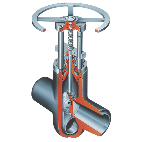
One of the best known is the valve shown, commonly referred to as a parallel slide gate valve. The closure member consists of two discs with springs in between. The duties of these springs are to keep the upstream and downstream seatings in sliding contact and to improve the seating load at low fluid pressures. The discs are carried in a belt eye in a manner that prevents their unrestrained spreading as they move into the fully open valve position.
The flow passage of this particular parallel slide gate valve is venturi shaped. The gap between the seats of the fully open valve is bridged by an eyelet to ensure a smooth flow through the valve. The advantages offered by this construction include not only economy of construction but also a reduced operating effort and lower maintenance cost. The only disadvantage is a slight increase in pressure loss across the valve.
The seating stress reaches its maximum value when the valve is nearly closed, at which position the pressure drop across the valve is near
maximum; but the seating area in mutual contact is only a portion of the total seating area. As the disc travels between the three-quarter closed to the nearly closed valve position, the flowing fluid tends to tilt the disc into the seat bore, so heavy wear may occur in the seat bore and on the outer edge of the disc. To keep the seating stress and corresponding seating wear within acceptable limits, the width of the seatings must be made appropriately wide. Although this requirement is paradoxical in that the seating width must be small enough to achieve a high seating stress but wide enough to keep seating wear within acceptable limits, the fluid tight- ness that is achieved by these valves satisfies the leakage criterion of the steam class, provided the fluid pressure is not too low.
Parallel slide gate valves have other excellent advantages: the seatings are virtually self-aligning and the seat seal is not impaired by thermal movements of the valve body. Also, when the valve has been closed in the cold condition, thermal extension of the stem cannot overload the seatings. Furthermore, when the valve is being closed, a high accuracy in the positioning of the discs is not necessary, thus an electric drive for the valve can be travel limited. Because an electric drive of this type is both economical
and reliable, parallel slide gate valves are often preferred as block valves in larger power stations for this reason alone. Of course, parallel slide gate valves may be used also for many other services such as water, in particular boiler feed water—and oil.
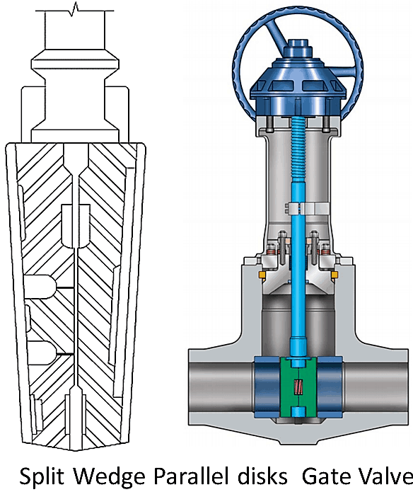
A variation of the parallel slide gate valve used mainly in the U.S. is fitted with a closure member such as the one shown . The closure member consists of two discs with a wedging mechanism in between, which, on contact with the bottom of the valve body, spreads the discs apart. When the valve is being opened again, the wedging mechanism releases the discs. Because the angle of the wedge must be wide enough for the wedge to be self-releasing, the supplementary seating load from the wedging action is limited.
To prevent the discs from spreading prematurely, the valve must be mounted with the stem upright. If the valve must be mounted with the stem vertically down, the wedge must be appropriately supported by a spring.
The performance characteristic attributed to parallel slide gate valves also applies largely to this valve. However, solids carried by the flowing fluid and sticky substances may interfere with the functioning of the wedging mechanism. Also, thermal extension of the stem can overload the seatings. The valve is used mainly in gas, water, and oil services.
Conventional parallel gate valves may also be fitted with soft seatings, as in the valve shown. The closure member consists here of a disc that carries two spring-loaded floating seating rings. These rings are provided with a bonded O-ring on the face and a second O-ring on the periphery. When the disc moves into the closed position, the O-ring on the face of the floating seating ring contacts the body seat and produces the initial fluid seal. The fluid pressure acting on the back of the seating ring then forces the seatings into still closer contact.
Because the unbalanced area on the back of the floating rings is smaller than the area of the seat bore, the seating load for a given fluid pressure and valve size is smaller than in the previously described valves. However, the valve achieves a high degree of fluid tightness by means of the O-ring even at low fluid pressures. This sealing principle also permits double block and bleed.
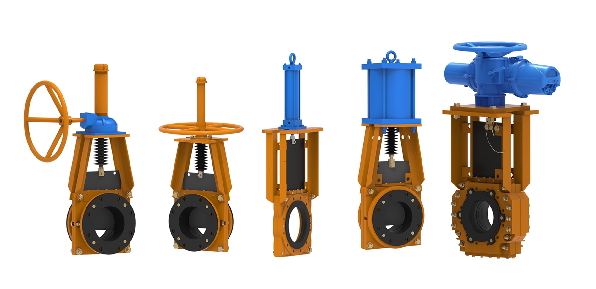
The parallel gate valve shown is known as the knife gate valve, and is designed to handle slurries, including fibrous material. The valve owes its ability to handle these fluids to the knife-edged disc, which is capable of cutting through fibrous material, and the virtual absence of a valve body cavity. The disc travels in lateral guides and is forced against the seat by lugs at the bottom. If a high degree of fluid tightness is required, the valve may also be provided with an O-ring seat seal.