An introduction to control valve
An introduction to control valve
A control valve is used in the oil and gas industry to regulate the flow rate of the fluid in a pipeline or process (and the related process parameters as pressure, temperature, and level) according to signals managed by a controller. The role of a flow control valve in the complex petrochemical process is key, as the multiple loops involved in the process should be kept under strict and dynamic control to make sure that the process, as a whole, works as intended and produces the desired output in terms of quantity, quality and time.
The application of flow control valves is increasing in the last years, due to growing process automation in most industries.
These type of valves are used in irrigation systems, water treatment plants, oil and gas plants, power generation, fire prevention systems, food processing industries by streamlining the response to changes in processes and providing greater safety to personnel and equipment.
A flow control valve used in the oil and gas industry can have a globe, butterfly, or ball shape, and is available in multiple material grades and sizes. The most used type of actuator is the air-operated, as it involves less ancillary equipment (as cabling, switchgear) when compared to other types of actuators.
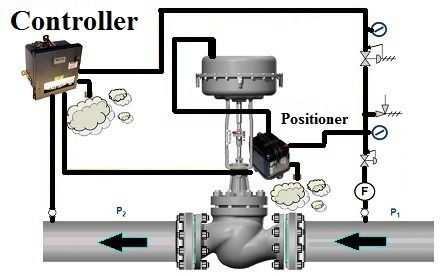
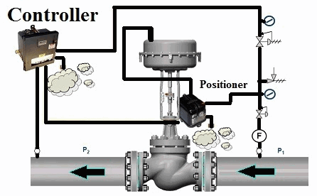
The opening and closing of the valve and its regulation are done by the combined effect of an electronic controller, a positioner and the actuator of the valve (which can be electric, pneumatic or hydraulic).
The actuator opens and closes the control valve in response to changes in key process parameters, such as changes in pressure, level, temperature, and flow.
By such action, the process parameters are maintained within the required target range to make sure the process, as a whole, works as intended and produces an end product in the desired quantity and quality.
FLOW CONTROL VALVE COMPONENTS
The main components of a control valve are:
- the valve body: where the modulating element is contained and operates
- the positioner: which is the element to control the degree of the valve opening and is mounted on the body of the valve
- the actuator: is the device that is used to move the modulating element of the valve, for example, the ball (ball valves), the disc (butterfly) or the stem (globe valves)
- the controller
FLOW CONTROL VALVE ACTUATORS
The selection of actuators is based on the required thrust of the rod and the movement of the valve.
Engineers must determine if the diagram or piston actuator is the most suitable type. Actuators are the primary energy source used to move and position the flow control element within the valve body.
A variety of types are available, including pneumatic, electric, hydraulic, electro-hydraulic and manual. Pneumatic actuators are the most widely used for throttling applications.
Considered the standard for automatic control for more than a century, three types of pneumatic actuators are available: piston, spring-and-diaphragm, and rotary vane. The first two can be adapted for use on either rotary or sliding-stem valves; the latter is used only on rotary valves.
FLOW CONTROL VALVE ACCESSORIES
Normally, the selection of accessories such as positioners transducers, boosters, solenoid valves, limit switches, handwheels and travel stop, snubbers, regulators, transmission lines, is based on engineering specifications.
Cost is a major factor in material selection.
Not just the cost of material in dollars per pound, but also the cost of fabrication and inspection contribute to the uninstalled cost of the valve. Installed cost includes not only the cost of installation but also the cost of any damage from improper installation and costs the inspection.
The latter consists of such things as analysis of material chemistry, radiographic and surface examination of castings and welds, and check to see that the installed valve is the correct one and that it is properly oriented.
The selection of the appropriate or optimal control valve type depends on the particular study of the pipe system and the conditions of its fluid, but the size of the control valve should be such that pressure drops through it and not the drop of pressure of the pipe is the one that controls the flow.
All valves, including steam control valves, are designed to meet an allowable internal leakage standard (FCI / ANSI). The higher the number of leaks, the lower the permissible internal leakage rate.
A Class I valve will have the highest internal leakage rate and usually the lowest cost; While a Class VI valve will have the lowest allowable internal leakage rate. Steam valves must be specified to have a leak rate of not less than Class IV. A class IV steam control valve will maintain a long service life.
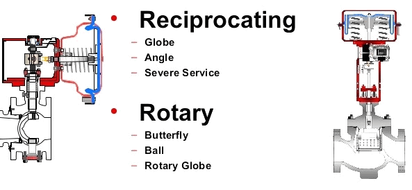
FLOW CONTROL VALVES TYPES
Control valves can be classified into two main types, based on the stem movement:
- Linear motion/reciprocating: globe (straight, angle, 3-way), diaphragm and, pinch control valves
- Rotary stem: ball, butterfly and, plug control valves types
Globe control valves can be either single or double seat.
CONTROL VALVE SELECTION
Process engineers must consider many factors to select the correct control valve. The general criteria to be considered for selection are summarized below:
- Type of control; the degree of control; the degree of shutoff.
- Design temperature; design pressure; allowable pressure drop.
- Fluid corrosivity; fluid erosion properties; other characteristics, such as fouling or coking.
- Inherent characteristics, such as valve Cv: degree of hazard from leakage; heat or cold conservation; cost.
As the design criteria are known, process engineers can proceed to make a selection of the correct type of control valve and related equipment, as well as the material of the valve itself.
The next step is to create the detailed specification (generally drafted by a specialized piping engineer) and create a purchase specification describing the valve for suppliers.
The specification should contain, as minimum: a description of the type of control valve (rotary, sliding); bore size and pressure rating; end-connections; type of body joints; material specification for body components, trim, gaskets and bolting; positioner and controller requirements; a reference to an industry design standard for type of valve.
Generally, a computerized system help engineers determine the most suited control valve and its features based on process parameters.
CONTROL VALVES INSTALLATION
- Always expand the discharge steam line piping at least one pipe diameter. It is not uncommon to expand the discharge piping at least two or three pipe diameters. It should be noted that the expansion of the pipe reduces the valve outlet velocities thus prolonging the valve life. The valve manufacturer will provide the appropriate pipe size after the control valve. Match the pipe size to the heat transfer inlet connection.
- The distance after the steam control valve should be at least ten pipe diameters before the inlet connection of any heat transfer. In pressure reduction applications at least 20 horizontal pipe diameters must be left before a change of flow direction.
- The control valve must always be installed in a horizontal vapor line, never vertically.
- It is more important to properly select the valve at low flow operating conditions that at its assumed high flow operating conditions.
- Bypass valves must be used in the control valve installation. The by-pass valve is used to allow the personnel of the industrial facility to operate the process without the control valve if valve failure or maintenance reactive, preventive and predictive.
- Installing pressure gauges before and after the steam control valve allows the line diagnostics in real time. The importance of proper installation cannot be overstated. In many cases, the source of a troublesome startup can be traced to a control valve that is not properly installed. It is strongly recommended that personnel with an instrumentation background be used at least to supervise the installation and setup of control valves.