Valve Review: Wedge Gate Valve

Wedge gate valves differ from parallel gate valves in that the closure member is wedge-shaped instead of parallel, as shown in Figure. The purpose of the wedge shape is to introduce a high supplementary seating load that enables metal-seated wedge gate valves to seal not only against high, but also low, fluid pressures. The degree of seat tightness that can be achieved with metal-seated wedge gate valves is therefore potentially higher than with conventional metal-seated parallel gate valves.
However, the upstream seating load is not normally high enough to permit block-and-bleed operation of metal-to-metal seated wedge gate valves. The bodies of these valves carry guide ribs, or slots, in which the disc travels. The main purpose of these guides is to carry the wedge away from the downstream seat except for some distance near the closed valve position so as to minimize wear between the seatings. A second purpose of the guides is to prevent the disc from rotating excessively while travel- ling between the open and closed valve positions. If some rotation occurs, the disc will initially jam on one side between the body seatings and the rotate into the correct position before travelling into the final seating position.
There are also types of wedge gate valves that can dispense with a wedge guide, such as the valve shown in Figure in which the wedge is carried by the diaphragm. Compared with parallel gate valves, wedge gate valves also have some negative features: • Wedge gate valves cannot accommodate a follower conduit as conveniently as parallel gate valves can. • As the disc approaches the valve seat, there is some possibility of the seatings trapping solids carried by the fluid. However, rubber-seated wedge gate valves, as shown in Figure are capable of sealing around small trapped solids.
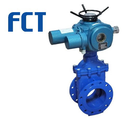
An electrical drive for wedge gate valves is more complicated than for parallel gate valves in that the drive must be torque-limited instead of travel-limited. The operating torque of the drive must thereby be high enough to effect the wedging of the wedge into the seats while the valve is being closed against the full differential line pressure. If the valve is closed against zero differential pressure, the wedging of the wedge into the seats becomes accordingly higher. To permit the valve to be opened again against the full differential pressure, and to allow also for a possible increase of the operating effort due to thermal movements of the valve parts, the operator must be generously sized. The limitations of wedge gate valves are otherwise similar to those of parallel gate valves. Efforts to improve the performance of wedge gate valves led to the development of a variety of wedge designs; the most common ones are described in the following section.
The sealing reliability of gate valves with a plain wedge can be improved by elastomeric or plastic sealing elements in either the seat or the wedge.
Please also have a look on:
For globe control valve: https://www.fctvalve.com/globe-control-valve
For three way control valve: https://www.fctvalve.com/three-way-control-valve
For angle control valve: https://www.fctvalve.com/three-way-control-valve
For butterfly valve: https://www.fctvalve.com/butterfly-control-valve
For ball control valve: https://www.fctvalve.com/ball-v-ball-control-valve
For Eccentric Rotary Plug Control Valve : https://www.fctvalve.com/eccentric-rotary-plug-control-valve
For diaphragm control valve: https://www.fctvalve.com/diaphragm-control-valve
For desuperheater control valve: https://www.fctvalve.com/desuperheater-control-valve
For PTFE globe control valve: https://www.fctvalve.com/ptfe-lined-globe-control-valve