Valve Review: Conduit Gate Valves
Conduit Gate Valves
All four types of valves are provided with floating seats that are forced against the disc by the fluid pressure.
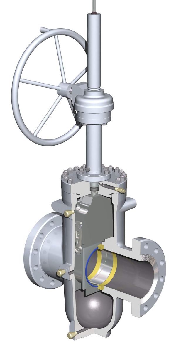
The seats of the conduit gate valve shown in Figure are faced with PTFE and sealed peripherally by O-rings. The disc is extended at the bottom to receive a porthole. When the valve is fully open, the porthole in the disc engages the valve ports so that the disc seals the valve body cavity against the ingress of solids. The sealing action of the floating seats also permits double block and bleed. If the seat seal should fail in service, a temporary seat seal can be produced by injecting a sealant into the seat face.
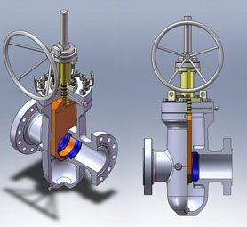
The conduit gate valve shown in Figure differs from the previous one in that the disc consists of two halves with a wedge-shaped 
interface. These halves are interlinked so that they wedge apart when being moved into the fully open or closed positions, but relax in the intermediate position to permit the disc to travel. Depending on the use of the valve, the face of the floating seats may be metallic or provided with a PTFE insert. To prevent the ingress of solids into the valve body cavity during all stages of disc travel, the floating seats are provided with skirts, between which the disc travels. This valve likewise permits double block and bleed. Also, should the seat seal fail in service, a temporary seat seal can be provided by injecting a sealant into the seat face.

The sealing action of the conduit gate valve shown in Figure depends on a sealant that is fed to the downstream seat face each time the valve is operated. For this purpose, the floating seats carry reservoirs that are filled with a sealant and topped by a floating piston. The entire valve chamber is, furthermore, filled with a grease that transmits the fluid pressure to the top of the piston of the downstream reservoir. The closure member consists of two discs, which are spread apart by springs. Both the sealant and the body arease can be replenished from the outside while the valve is in service. Each reservoir filling is sufficient for more than 100 valve operations. This mode of sealing achieves a high degree of fluid tightness at high fluid pressures.
The conduit gate valve shown in Figure is especially designed for the hydraulic transport of coal and ore, and the transport of heavily dust- laden gases. The gate, which consists of a heavy wear-resistant plate with a porthole in the bottom, slides between two floating seats that are highly pre- stressed against the disc by means of disc springs. To prevent any possible entry of solids into the body cavity, the seats are provided with skirts for the full travel of the disc. The faces of the disc and seats are metallic and highly polished. The valve chamber is, furthermore, filled with a lubricant that ensures lubrication of the seating faces.
Valve Bypass
The seating load of the larger parallel gate valves (except those with floating seats) can become so high at high fluid pressures that friction between the seatings can make it difficult to raise the disc from the closed position. Such valves are therefore frequently provided with a valve bypass line, which is used to relieve the seating load prior to opening the valve. There are no fast rules about when to employ a bypass, and the manufacturer’s recommendation may be sought. Some standards of gate valves contain recommendations on the minimum size of the bypass.
In the case of gases and vapors, such as steam, that condense in the cold downstream system, the pressurization of the downstream system can be considerably retarded. In this instance, the size of the bypass line should be larger than the minimum recommended size.
Pressure-Equalizing Connection
In the case of the conventional double-seated parallel gate valves shown in Figure , thermal expansion of a liquid trapped in the closed valve chamber will force the upstream and downstream discs into more intimate contact with their seats, and cause the pressure in the valve chamber to rise. The higher seating stress makes it in turn more difficult to raise the discs, and the pressure in the valve chamber may quickly become high enough to cause a bonnet flange joint to leak or the valve body to deform. Thus, if such valves are used to handle a liquid with high thermal expansion, they must have a pressure-equalizing connection that connects the valve chamber with the upstream piping.
The pressure rise in the valve chamber may also be caused by the evaporation of trapped condensate, as in the case in which these valves are closed against steam. Both the valve chamber and the upstream piping are initially under pressure and filled with steam. Eventually, the steam will cool, condense, and be replaced to some extent with air.
Upon restart, the steam will enter the upstream piping and, since the upstream seat is not normally fluid-tight against the upstream pressure, will enter the valve chamber. Some of the new steam will also condense initially until the valve body and the upstream piping have reached the saturation temperature of the steam.
When this has happened, the steam begins to boil off the condensate. If no pressure-equalizing connection is provided, the expanding steam will force the upstream and downstream discs into more intimate contact with their seats, and raise the pressure in the valve chamber. The magnitude of the developing pressure is a function of the water temperature and the degree of filling of the valve chamber with water, and may be obtained from Figure.
The pressure-equalizing connection may be provided by a hole in the upstream disc or by other internal or external means. Some makers of parallel gate valves of the types shown in Figure combine the bypass line with a pressure-equalizing line if the valve is intended for steam.
Applications
Duty:
Stopping and starting flow
Infrequent operation
Service: Gases
Please also have a look on:
For globe control valve: https://www.fctvalve.com/globe-control-valve
For three way control valve: https://www.fctvalve.com/three-way-control-valve
For angle control valve: https://www.fctvalve.com/three-way-control-valve
For butterfly valve: https://www.fctvalve.com/butterfly-control-valve
For ball control valve: https://www.fctvalve.com/ball-v-ball-control-valve
For Eccentric Rotary Plug Control Valve : https://www.fctvalve.com/eccentric-rotary-plug-control-valve
For diaphragm control valve: https://www.fctvalve.com/diaphragm-control-valve
For desuperheater control valve: https://www.fctvalve.com/desuperheater-control-valve
For PTFE globe control valve: https://www.fctvalve.com/ptfe-lined-globe-control-valve