Valve Review: Functions of manual valves
Valve Review: Functions of manual valves
A manual valve is considered to be a valve that is operated by plant personnel directly, by the use of either a handwheel/wrench or an on/off actuator in the case of shutdown valves. Certain automated valves with actuators are also supplied with handwheels to allow manual operation in the event of power failure.
Manual valves serve three major functions in fluid-handling systems: stopping and starting flow, controlling flow rate, and diverting flow. Valves for stopping and starting flow are frequently employed also for controlling flow rate, and vice versa, while valves for diverting flow are designed for that single purpose.
GROUPING OF VALVES BY METHOD OF FLOW REGULATION
Manual valves may be grouped according to the way the closure member moves onto the seat. Four groups of valves are thereby distinguishable:
1. Closing-down valves. A stopper-like closure member is moved to and from the seat in the direction of the seat axis.
2. Slide valves. A gate-like closure member is moved across the flow passage.
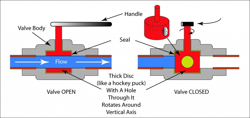
3. Rotary valves. A plug or disc-like closure member is rotated within the flow passage, around an axis normal to the flow stream.
4. Flex-body valves. The closure member flexes the valve body.
Each valve group represents a number of distinct types of valves that use the same method of flow regulation, but differ in the shape of the closure member. For example, plug valves and butterfly valves are both rotary valves, but of a different type. In addition, each valve is made in numerous variations to satisfy particular service needs. Figure below illustrates the principal methods of flow regulation and names the types of valves, which belong to a particular valve group.
SELECTION OF VALVES
The method by which the closure member regulates the flow and the configuration of the flow path through the valve impart a certain flow characteristic to the valve, which is taken into account when selecting a valve for a given flow-regulating duty.
Valves for Stopping and Starting Flow
These valves are normally selected for low flow resistance and a straight- through flow passage. Such valves are slide valves, rotary valves, and flex-body valves. Closing-down valves offer by their tortuous flow pas- sage a higher flow resistance than other valves and are therefore less frequently used for this purpose. However, if the higher flow resistance can be accepted—as is frequently the case—closing-down valves may likewise be used for this duty.
Valves for Controlling Flow Rate
These are selected for easy adjustment of the flow rate. Closing-down valves lend themselves for this duty because of the directly proportional relationship between the size of the seat opening and the travel of the closure member. Rotary valves and flex-body valves also offer good throttling control, but normally only over a restricted valve-opening range.

Gate valves, in which a circular disc travels across a circular seat open- ing, achieve good flow control only near the closed valve position and are therefore not normally used for this duty.
Valves for Diverting Flow
These valves have three or more ports, depending on the flow diversion duty. Valves that adapt readily to this duty are plug valves and ball valves.
For this reason, most valves for the diversion of flow are one of these types. However, other types of valves have also been adapted for the diversion of flow, in some cases by combining two or more valves that are suitably interlinked.
Valves for Fluids with Solids in Suspension
If the fluid carries solids in suspension, the valves best suited for this duty have a closure member that slides across the seat with a wiping motion. Valves in which the closure member moves squarely on and off the seat may trap solids and are therefore suitable only for essentially clean fluids unless the seating material can embed trapped solids.
Valve End Connections
Valves may be provided with any type of end connection used to connect piping. The most important of these for valves are threaded, flanged, and welding end connections.
Threaded end connections.
These are made, as a rule, with taper or parallel female threads, which screw over tapered male pipe threads. Because a joint made up in this way contains large leakage passages, a sealant or filler is used to close the leakage passages. If the construction material of the valve body is weldable, screwed joints may also be seal welded. If the mating parts of the joint are made of different but weldable materials with widely differing coefficients of expansion, and if the operating temperature cycles within wide limits, seal welding the screwed joint may be necessary.
Valves with threaded ends are primarily used in sizes up to DN 50 (NPS 2). As the size of the valve increases, installing and sealing the joint become rapidly more difficult. Threaded end valves are available, though, in sizes up to DN 150 (NPS 6).
To facilitate the erection and removal of threaded end valves, couplings are used at appropriate points in the piping system. Couplings up to DN 50 (NPS 1) consist of unions in which a parallel thread nut draws two coupling halves together. Larger couplings are flanged.
Codes may restrict the use of threaded end valves, depending on application.
Flanged end connections
These permit valves to be easily installed and removed from the pipeline. However, flanged valves are bulkier than threaded end valves and correspondingly dearer. Because flanged joints are tightened by a number of bolts, which individually require less tighten- ing torque than a corresponding screwed joint, they can be adapted for all sizes and pressures. At temperatures above 350◦C (660◦F), however, creep relaxation of the bolts, gasket, and flanges can, in time, noticeably lower the bolt load. Highly stressed flanged joints can develop leakage problems at these temperatures.
Flange standards may offer a variety of flange face designs and also recommend the appropriate flange face finish. As a rule, a serrated flange face finish gives good results for soft gaskets. Metallic gaskets require a finer flange finish for best results. Chapter 2 discusses the design of gaskets.
Welding end connections. These are suitable for all pressures and temperatures, and are considerably more reliable at elevated temperatures and other severe applications than flanged connections. However, removal and re-erection of welding end valves is more difficult. The use of welding end valves is therefore normally restricted to applications in which the valve is expected to operate reliably for long periods, or applications which are critical or which involve high temperatures.
Welding end valves up to DN 50 (NPS 2) are usually provided with welding sockets, which receive plain end pipes. Because socket weld joints form a crevice between socket and pipe, there is the possibility of crevice corrosion with some fluids. Also, pipe vibrations can fatigue the joint. Therefore, codes may restrict the use of welding sockets.
Valve Ratings
The rating of valves defines the pressure-temperature relationship within which the valve may be operated. The responsibility for determining valve ratings has been left over the years largely to the individual manufacturer. The frequent U.S. practice of stating the pressure rating of general purpose valves in terms of WOG (water, oil, gas) and WSP (wet steam pressure) is a carryover from the days when water, oil, gas, and wet steam were the substances generally carried in piping systems. The WOG rating refers to the room-temperature rating, while the WSP rating is usually the high temperature rating. When both a high and a low temperature rating is given, it is generally understood that a straight-line pressure-temperature relationship exists between the two points.
Some U.S. and British standards on flanged valves set ratings that equal the standard flange rating. Both groups of standards specify also the permissible construction material for the pressure-containing valve parts. The rating of welding end valves corresponds frequently to the rating of flanged valves. However, standards may permit welding end valves to be designed to special ratings that meet the actual operating conditions.36 If the valve contains components made of polymeric materials, the pressure- temperature relationship is limited, as determined by the properties of the polymeric material. Some standards for valves containing such materials as ball valves specify pressure-temperature limits for the valve. Where such standards do not exist, it is the manufacturer’s responsibility to state the pressure and temperature limitations of the valve.
Valve Selection Chart
The valve selection chart shown in Table is based on the foregoing guidelines and may be used to select the valve for a given flow-regulating duty. The construction material of the valve is determined on one hand by the operating pressure and temperature in conjunction with the appli- cable valve standard, and on the other hand by the properties of the fluid, such as its corrosive and erosive properties. The selection of the seating material is discussed in Chapter 2. The best approach is to con- sult the valve manufacturer’s catalog, which usually states the standard construction material for the valve for given operating conditions. How- ever, it is the purchaser’s responsibility to ensure that the construction material of the valve is compatible with the fluid to be handled by the valve.
If the cost of the valve initially selected is too high for the purpose of the valve, the suitability of other types of valves must be investigated. Sometimes a compromise has to be made.
This selection procedure requires knowledge of the available valve types and their variations, and possibly knowledge of the available valve standards. This information is given in the following sections.
