Gate Valve for Piping (API 600, 602, 603)
DEFINITION
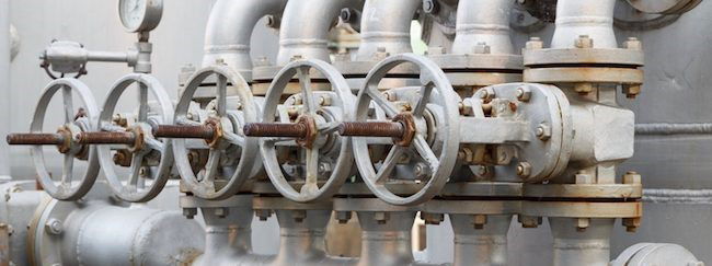
Gate valves are on-off valves to open and close the flow of the fluid in a pipeline. The valve is opened and/or closed by the vertical movement of a disc on the valve’s seat.
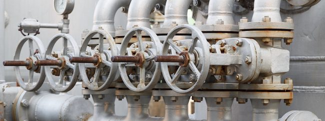
The main advantages of this type of valve are:
- Easy to maintain and disassemble
- Optimal as a shut off valve
- Bidirectional
- Low cost
- Can be used with slurries and viscous liquids
- Available in large sizes
- Inherently fire-safe (when used with a metal sheet)
The disadvantages are:
- Slow open and close time
- Low-pressure limitations
- Erosion of the seat and disk can occur
- Poor throttling characteristics
- Difficult to repair
KEY SPECIFICATIONS
The most important specifications covering gate valves used for piping systems are:
- API 600: cast carbon and alloy valves
- API 603: stainless steel valves
- API 602/BS 5352: forged valves
- API 6D: slab and through conduit valves for pipelines
- ASME ANSI B16.34: pressure ratings
- ASME ANSI B16.10: face to face dimensions
- ASME ANSI B16.5: flanged ends
- ASME ANSI B16.25: butt weld ends
- ASME ANSI B16.47: flanged ends for bore sizes above 24 inches
- API-598: valves testing
GATE VALVE TYPES
CAST STEEL
This is the most common type, covered by the API 600 (carbon and alloy steel) and API 603 (stainless steel and higher grades) specifications. Cast steel gate valves are available in sizes above 2 inches, and up to 80 inches.
FORGED STEEL
Forged steel valves are used for small bore piping, generally below 2 inches in diameter. The API 602 and BS 5352 specifications cover this type of gate valves.
API 6D FOR PIPELINES (THROUGH-CONDUIT)
These are gate valves for pipelines and are available in two key designs, slab and expanding gate.
PRESSURE SEAL
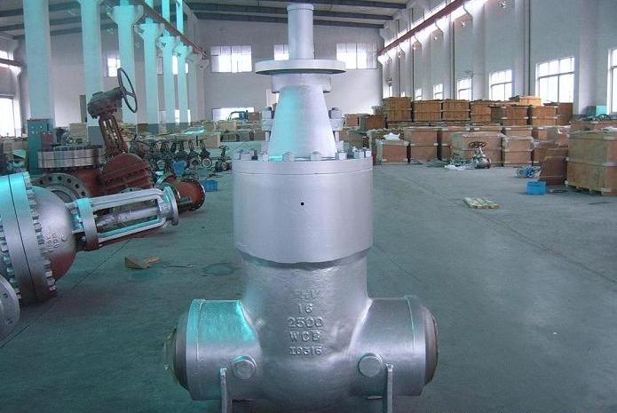
Pressure seal gate valves are used for high-pressure applications. The most common types of valves for high-pressure application are the flexible wedge and the parallel slide pressure seal valve. They are generally available with cast or forged bodies, in dimensions from 2 to 24 inches and pressure rating from 600# to 4500#, with socket weld or buttweld, ends to ensure tight flanged joint connections (but flanged ends are also possible).
KNIFE TYPE
Knife gate valves were originally introduced within the pulp and paper industry, where standard shut-off valves could not properly operate due to the nature of the fluids conveyed during the paper production process.
Knife valves should never be used as modulating valves (to regulate the flow) as the fluid flowing through a partly closed valve would generate vibration and erode both the disk and the seat.
Therefore, knife valves should be used completely closed or opened like any other type of gate valve (globe valves are recommended to regulate the flow).
Lastly, to protect the valve against the impact of the water hammer effect, knife valves feature a very slow opening and closing speed.
A Knife valve can be manufactured in materials from ductile iron to stainless steel and in sizes between 2 and 24 inches (generally with cast bodies) with low-pressure ratings (< 300 lbs).
There are many different variants of knife valves, such as the soft-seated (resilient type, with elastomer seats) and the metal seated (the seat and the disc generate a metal-to-metal seal), the slide gate and bonneted types.
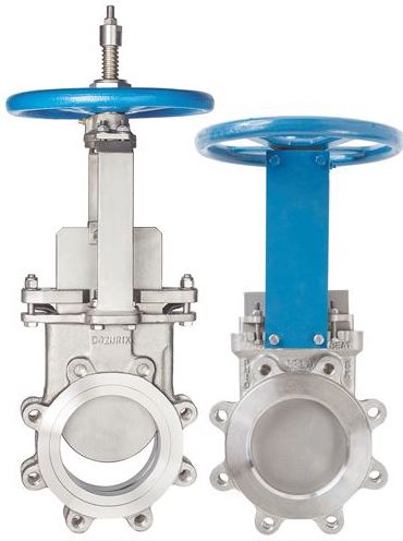
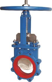
Soft seat knife gate valve.
A metal seated knife gate valve (left) and resilient, a soft-seated valve (right side).
The differences with standard design are:
- A standard valve is available with flanged, butt weld and socket weld connections (knife have lugged or wafer connections mainly)
- A standard valve has a V-ring packing set that seals the shaft that is attached to the gate. Knife valves feature instead of a packing gland area that seals around the gate
- Gate valves are bidirectional, whereas the knife type is generally uni-directional
- A knife valve has a smaller profile than the ANSI gate valve, which is more bulky and refined
- Knife gate valves are lighter and cheaper than API and ASME types
GATE VALVE vs. BALL/GLOBE VALVES
VS. BALL VALVE
What is the difference between a gate and a ball valve?
Ball and gate valves execute the same function, i.e. they can open and close the flow of the fluid of the pipeline. However, there are a few differences between these two types of valves:
- Ball valves feature a stem and a ball, which turns horizontally to shut off the fluid’s passageway. Gate valves instead close the passageway by the combined action of a wedge (which is a rectangular or round “gate”) and a seat.
- Ball valves suit applications that require a tight shut-off, without pressure drop (gate valves, instead, create a small pressure drop).
- Gate valves belong to the family of “on-off” valves, ball valves to the family of “quarter-turn” valves
- Ball valves feature very tight seals and are way less prone to leaks than gate valves
- Ball valves have a longer life cycle and a lower failure rate than gate valves
- Ball valves are easier to use than gate valves but tend to be more expensive
VS. GLOBE VALVE
What is the difference between a gate and a globe valve?
A gate valve cannot be used to modulate and regulate the flow of the fluid, as its high speed would damage the wedge and the seats in case of partial opening or closing of the valve, and they cannot be used for quick opening and close operations either.
Fluid throttling and regulation, and repeated open/close operations shall be executed using globe valves instead of gate valves.
GATE VALVE DIAGRAM
The gate valve diagram shows the standard assembly drawing of a gate valve. Many design variations are possible, depending on the gate valve parts configuration:
- body material construction: forged or cast
- bonnet design and connection: can be standard or pressure seal (high-pressure gate valves), bolted/welded bonnet, etc.
- ends connection: gate valves are available with multiple valves ends designs (socket weld and threaded for forged gate valves and butt weld for cast body gate valves)
- wedge type (solid/flexible/split/parallel slide): see details below in this article
- stem type (rising/ non-rising): see details below
- manufacturing norm: API vs EN gate valves have slightly different designs
- type of valve operation: manual, gear or pneumatic/hydraulic/electric actuation
- etc.
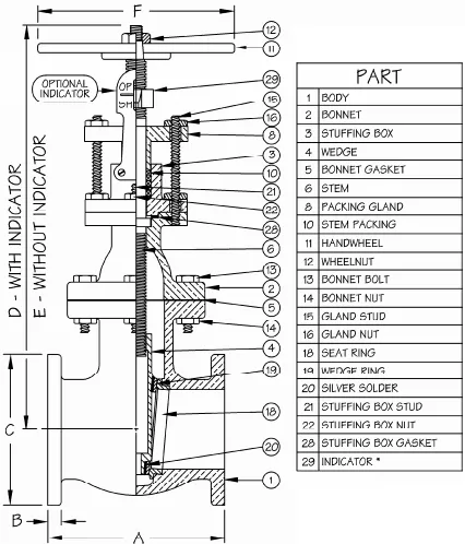
Gate valve diagram showing the key parts of a gate valve for piping
WEDGE TYPES
The image below shows how the gate valve wedge opens and closes the flow of the fluid by application of a vertical movement (which can be manual or operated by an actuator).
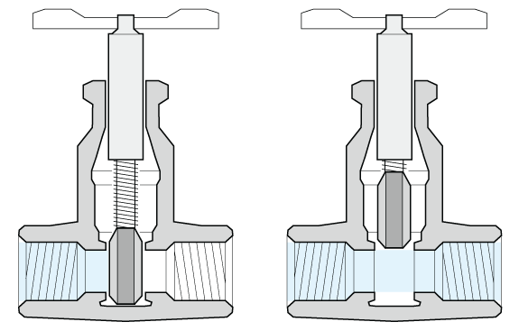
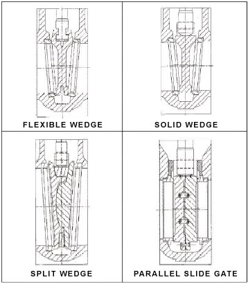
The wedge is positioned between two parallel (or oblique) seats which are perpendicular to the flow. The fluid flows horizontally through gate valves and is not subject to pressure drops. Wedges can be of different types:
- “solid-wedge” (in this case, the wedge is manufactured with a solid piece of steel)
- “flexible-wedge” (in this case the disc features cuts around its perimeter to enhance the ability of the valve to correct changes in the angle between the seats)
- “split-wedge” (two pieces construction disc, to enforce self-alignment of the wedge on the seats)
- “parallel-slide wedge“
STEM TYPES
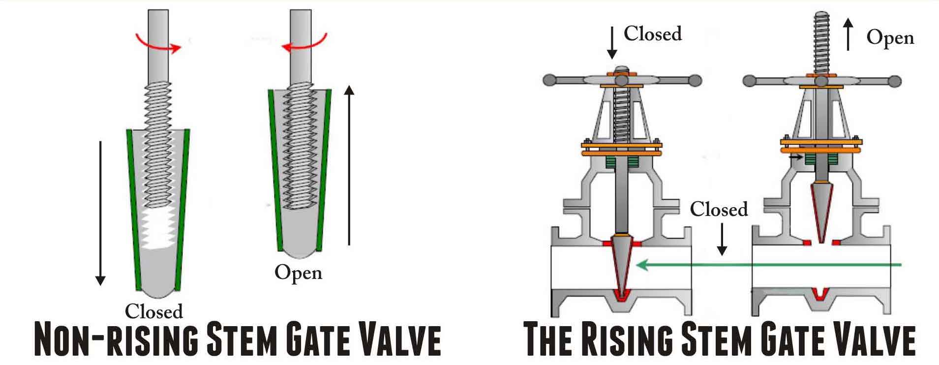
A gate valve may have a rising stem (in this case, the stem rises above the handwheel if the valve is opened) or a non-rising stem (the stem doesn’t move above the valve when it is opened).
OS&Y VS. IS&Y DESIGN
It is very frequent to see the term “OS&Y” associated with gate valves.
This term means that when the handle of a gate valve is rotated to open or close the valve, it directly raises and lowers the disc by interacting with the stem of the valve.
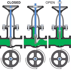
In an “OS&Y gate valve”, the stem of the valve itself raises and lowers outside the body of the valve in a very visible way, while the handle remains in a fixed position.
When the stem raises, the disc inside the body of the valve rises from the seat letting the fluid flow through the valve (valve in open position).
Therefore with an OS&Y gate valve, the actual position of a valve (closed or open) is always evident to the operators.
Differently, the valve position is not immediately visible for “IS&Y gate valves” (inside screw and yoke), as the stem of the valve does not raise or lowers outside the valve when the handle is rotated.
GATE VALVE MATERIALS
BODY
The body of gate valves below 2 inches is generally made of forged steel (the most common body material grades are ASTM A105 for high-temperature service, ASTM A350 for low-temperature service and, ASTM A182 F304/F316 for corrosive service).
The bodies of gate valves of bore sizes above 2 inches are, instead, made of cast steel (the main cast grades are ASTM A216 WCB for high-temperature service, ASTM A351 for low-temperature conditions and ASTM A351 CF8 and CF8M – i.e. stainless steel 304 and 316 gate valves).
TRIM
The removable and replaceable parts of the valve are collectively defined as “trim” (for a gate valve: seat, disc, backseat and, stem).
The API 600 specification foresees a number of standard trim combinations, as illustrated below
| API TRIM # | BASE MATERIAL | MATERIAL FOR SEAT | MATERIAL FOR DISC | BACKSEAT MATERIAL | MATERIAL FOR STEM |
|---|---|---|---|---|---|
| 1 | 410 | 410 | 410 | 410 | 410 |
| 2 | 304 | 304 | 304 | 304 | 304 |
| 3 | F310 | 310 | 310 | 310 | 310 |
| 4 | Hard 410 | Hard 410 | 410 | 410 | 410 |
| 5 | Hardfaced | Stellite | Stellite | 410 | 410 |
| 5A | Hardfaced | Ni-Cr | Ni-Cr | 410 | 410 |
| 6 | 410 and Cu-Ni | Cu-Ni | Cu-Ni | 410 | 410 |
| 7 | 410 and Hard 410 | Hard 410 | Hard 410 | 410 | 410 |
| 8 | 410 and Hardfaced | Stellite | 410 | 410 | 410 |
| 8A | 410 and Hardfaced | Ni-Cr | 410 | 410 | 410 |
| 9 | Monel | Monel | Monel | Monel | Monel |
| 10 | 316 | 316 | 316 | 316 | 316 |
| 11 | Monel | Stellite | Monel | Monel | Monel |
| 12 | 316 and Hardfaced | Stellite | 316 | 316 | 316 |
| 13 | Alloy 20 | Alloy 20 | Alloy 20 | Alloy 20 | Alloy 20 |
| 14 | Alloy 20 and Hardfaced | Stellite | Alloy 20 | Alloy 20 | Alloy 20 |
| 15 | 304 and Hardfaced | Stellite | Stellite | 304 | 304 |
| 16 | 316 and Hardfaced | Stellite | Stellite | 316 | 316 |
| 17 | 347 and Hardfaced | Stellite | Stellite | 347 | 347 |
| 18 | Alloy 20 and Hardfaced | Stellite | Stellite | Alloy 20 | Alloy 20 |
MATERIAL SELECTION
| TRIM | RECOMMENDED SERVICE |
|---|---|
| 13% Cr, Type 410 Stainless Steel | For oil and oil vapors and general services with heat treated seats and wedges. |
| 13% Cr, Type 410 plus Hardfacing | Universal trim for general service requiring long service life up to 1100°F (593°C).* |
| Type 316 Stainless | For liquids and gases which are corrosive to 410 Stainless Steel, up to 1000°F (537°C).* |
| Monel | For corrosive service to 842°F (450°C) such as acids, alkalies, salt solutions, etc. |
| Alloy 20 | For corrosive service such as hot acids -49°F to 608oF (-45°C to 320°C). |
| NACE | Specially treated 316 or 410 trim combined optionally with B7M Bolts and 2HM nuts to meet NACE MR-01-75 requirements. |
| Full Stellite | Full hard faced trim, suitable for abrasive & severe services up to 1200°F (650°C). |
GATE VALVE DIMENSIONS
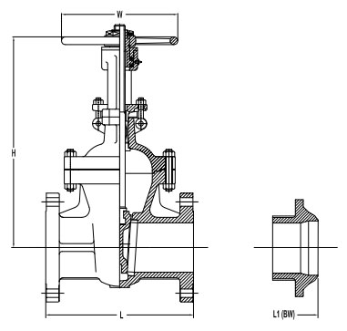
The tables show the dimensions and weights of API 600 gate valves (bolted bonnet / rising stem)
CLASS 150
Dimensions in inches (millimeters)
| GEAR OPERATOR RECOMMENDED FOR SIZE 10″ AND ABOVE | ||||
|---|---|---|---|---|
| Sizes | L | L1 (BW) | H (Open) | W |
| 2″ | 7 (180) | 8-1/2 (216) | 14-1/2 (368) | 8 (200) |
| 2-1/2″ | 7-1/2 (190) | 9-1/2 (241) | 17 (432) | 8 (200) |
| 3″ | 8 (200) | 11-1/8 (283) | 18 (457) | 8-7/8 (225) |
| 4″ | 9 (230) | 12 (305) | 22 (559) | 11 (279) |
| 5″ | 10 (254) | 15 (381) | 26 (660) | 12-3/4 (325) |
| 6″ | 10-1/2 (266) | 15-7/8 (403) | 30 (762) | 14 (356) |
| 8″ | 11-1/2 (290) | 16-1/2 (420) | 38-1/2 (978) | 14 (356) |
| 10″ | 13 (330) | 18 (457) | 46 (1168) | 18 (457) |
| 12″ | 14 (356) | 19 (502) | 55-1/4 (1403) | 20 (508) |
| 14″ | 15 (381) | 22 (559) | 60 (1524) | 21-1/2 (546) |
| 16″ | 16 (407) | 24 (610) | 74-7/8 (1902) | 24 (610) |
| 18″ | 17 (432) | 26 (660) | 79 (2007) | 27 (686) |
| 20″ | 18 (457) | 28 (711) | 87-1/2 (2223) | 28 (711) |
| 24″ | 20 (508) | 32 (813) | 105 (2667) | 31-1/2 (800) |
| 30″ | 24 (610) | 38 (965) | 130 (3302) | 43 (1092) |
| 36″ | 28 (711) | 44 (1118) | 162 (4115) | 51 (1295) |
CLASS 300
Dimensions in inches (millimeters)
| GEAR OPERATOR RECOMMENDED FOR SIZE 8″ AND ABOVE | ||||
|---|---|---|---|---|
| SIZES | L/L1 | H (OPEN) | W | |
| 2″ | 8-1/2 (216) | 16 (407) | 7-7/8 (200) | |
| 2-1/2″ | 9-1/2 (241) | 17-3/8 (442) | 7-7/8 (200) | |
| 3″ | 11-1/8 (283) | 19-3/4 (501) | 8-7/8 (225) | |
| 4″ | 12 (305) | 23-3/8 (594) | 9-7/8 (251) | |
| 5″ | 15 (381) | 23-3/4 (603) | 12-1/2 (318) | |
| 6″ | 15-7/8 (403) | 32-1/8 (816) | 14 (356) | |
| 8″ | 16-1/2 (420) | 41 (1041) | 15-3/4 (400) | |
| 10″ | 18 (457) | 48-3/8 (1229) | 17-3/4 (451) | |
| 12″ | 19-3/4 (501) | 57 (1448) | 20 (508) | |
| 14″ | 30 (762) | 62-1/2 (1588) | 22 (559) | |
| 16″ | 33 (838) | 69 (1753) | 25 (635) | |
| 18″ | 36 (914) | 80-1/2 (2045) | 28 (711) | |
| 20″ | 39 (991) | 91 (2311) | 35-1/2 (902) | |
| 24″ | 45 (1143) | 120-1/2 (3061) | 43 (1092) | |
CLASS 600
Dimensions in inches (millimeters)
| GEAR OPERATOR RECOMMENDED FOR SIZE 8″ AND ABOVE | ||||
|---|---|---|---|---|
| SIZES | L/L1 | H (OPEN) | W | |
| 2″ | 11-1/2 (290) | 16-1/2 (420) | 7-7/8 (200) | |
| 2-1/2″ | 13 (330) | 18 (457) | 8-7/8 (225) | |
| 3″ | 14 (356) | 20-1/8 (511) | 9-7/8 (251) | |
| 4″ | 17 (432) | 25 (635) | 14 (356) | |
| 5″ | 20 (508) | 30-1/2 (775) | 15-3/4 (400) | |
| 6″ | 22 (559) | 33-5/8 (854) | 17-3/4 (451) | |
| 8″ | 26 (660) | 42-3/8 (1076) | 20 (508) | |
| 10″ | 31 (787) | 49 (1245) | 25 (635) | |
| 12″ | 33 (838) | 68-1/2 (1740) | 27 (686) | |
| 14″ | 35 (889) | 69 (1753) | 31-1/2 (800) | |
| 16″ | 39 (991) | 74 (1880) | 35-1/2 (902) | |
| 18″ | 43 (1092) | 84-1/4 (2140) | 43 (1092) | |
| 20″ | 47 (1194) | 93-1/2 (2375) | 51 (1295) | |
| 24″ | 55 (1397) | 110 (2794) | 51 (1295) | |
CLASS 900
Dimensions in inches (millimeters)
| GEAR OPERATOR RECOMMENDED FOR SIZE 6″ AND ABOVE | ||||
|---|---|---|---|---|
| SIZES | L/L1 | H (OPEN) | W | |
| 2″ | 14-1/2 (368) | 26 (660) | 10-1/4 (260) | |
| 3″ | 15 (381) | 26-3/8 (670) | 11-1/2 (292) | |
| 4″ | 18 (457) | 30 (762) | 14 (356) | |
| 6″ | 24 (610) | 40-3/4 (1035) | 20 (508) | |
| 8″ | 29 (737) | 51 (1295) | 24 (610) | |
| 10″ | 33 (838) | 61 (1549) | 27 (686) | |
| 12″ | 38 (965) | 69-1/2 (1765) | 31-1/2 (800) | |
| 14″ | 40-1/2 (1029) | 77 (1956) | 35-1/2 (902) | |
| 16″ | 44-1/2 (1130) | 82-3/4 (2102) | 43 (1092) | |
CLASS 1500
Dimensions in inches (millimeters)
| GEAR OPERATOR RECOMMENDED FOR SIZE 6″ AND ABOVE | ||||
|---|---|---|---|---|
| SIZES | L/L1 | H (OPEN) | W | |
| 2″ | 14-1/2 (368) | 21-1/2 (546) | 11-1/2 (290) | |
| 3″ | 18-1/2 (470) | 27-1/8 (689) | 14 (356) | |
| 4″ | 21-1/2 (546) | 31-1/2 (800) | 20 (508) | |
| 6″ | 27-3/4 (705) | 45 (1143) | 24 (610) | |
| 8″ | 32-3/4 (832) | 53-1/2 (1359) | 27 (686) | |
| 10″ | 39 (991) | 65 (1651) | 35-1/2 (902) | |
| 12″ | 44-1/2 (1130) | 74 (1880) | 43 (1092) | |
| 14″ | 49-1/2 (1257) | 83-1/2 (2121) | 51 (1295) | |
| 16″ | 54-1/2 (1384) | 88 (2235) | 63 (1600) | |
CLASS 2500
Dimensions in inches (millimeters)
| GEAR OPERATOR RECOMMENDED FOR SIZE 6″ AND ABOVE | ||||
|---|---|---|---|---|
| SIZES | L/L1 | H (OPEN) | W | |
| 2″ | 17-3/4 (451) | 24-7/8 (632) | 12 (305) | |
| 3″ | 22-3/4 (578) | 36 (914) | 20 (508) | |
| 4″ | 26-1/2 (673) | 41-1/2 (1054) | 20 (508) | |
| 6″ | 36 (914) | 57 (1448) | 24 (610) | |
| 8″ | 40-1/4 (1022) | 63-3/8 (1610) | 24 (610) | |