Valve Review: Globe Valve
GLOBE VALVES
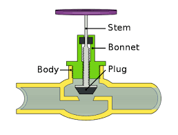
Globe valves are closing-down valves in which the closure member is moved squarely on and off the seat. It is customary to refer to the closure member as a disc, irrespective of its shape.
By this mode of disc travel, the seat opening varies in direct pro- portion to the travel of the disc. This proportional relationship between valve opening and disc travel is ideally suited for duties involving regulation of flow rate. In addition, the seating load of globe valves can be positively controlled by a screwed stem, and the disc moves with little or no friction onto the seat, depending on the design of seat and disc. The sealing capacity of these valves is therefore potentially high. On the debit side, the seatings may trap solids, which travel in the flowing fluid.
Globe valves may, of course, be used also for on-off duty, provided the flow resistance from the tortuous flow passage of these valves can be accepted. Some globe valves are also designed for low flow resistance for use in on-off duty. Also, if the valve has to be opened and closed frequently, globe valves are ideally suited because of the short travel of the disc between the open and closed positions, and the inherent robustness of the seatings to the opening and closing movements.
Globe valves may therefore be used for most duties encountered in fluid- handling systems. This wide range of duties has led to the development of numerous variations of globe valves designed to meet a particular duty at the lowest cost. The valves shown in Figures below are representative of the many variations that are commonly used in pipelines for the control of flow.
An inspection of these illustrations shows numerous variations in design detail. These are discussed in the following section.
Valve Body Patterns
The basic patterns of globe-valve bodies are the standard pattern, as in the valves shown in Figure below.
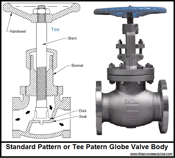
The standard-pattern valve body is the most common one, but offers by its tortuous flow passage the highest resistance to flow of the patterns available.
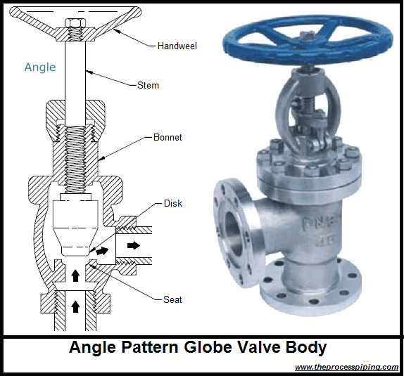
If the valve is to be mounted near a pipe bend, the angle-pattern valve body offers two advantages. First, the angle-pattern body has a greatly reduced flow resistance compared to the standard-pattern body. Second, the angle-pattern body reduces the number of pipe joints and saves a pipe elbow.

Valve Seatings
Globe valves may be provided with either metal seatings or soft seatings. In the case of metal seatings, the seating stress must not only be high but also circumferentially uniform to achieve the desired degree of fluid tightness. These requirements have led to a number of seating designs. The ones shown in below.

Flat seatings a have the advantage over other types of seatings in that they align readily to each other without having to rely on close guiding of the disc. Also, if the disc is moved onto the seat without being rotated, the seatings mate without friction. The resistance of the seating material to galling is therefore unimportant in this case. Deformation of the roundness of the seat due to pipeline stresses does not interfere with the sealability of the seatings as long as the seat face remains flat. If flow is directed from above the seat, the seating faces are protected from the direct impact of solids or liquid droplets travelling in the fluid.
By tapering the seatings, as shown in Figure b & c, and d, the seating stress for a given seating load can be greatly increased. However, the seating load can be translated into higher uniform seating stress only if the seatings are perfectly mated; that is, they must not be mated with the disc in a cocked position. Thus, tapered discs must be properly guided into the seat. Also, the faces of seat and disc must be perfectly round. Such roundness is sometimes difficult to maintain in larger valves where pipeline stresses may be able to distort the seat roundness. Furthermore, as the seatings are tightened, the disc moves further into the seat. Tapered seatings therefore tighten under friction even if the disc is lowered into the seat without being rotated. Thus the construction material for seat and disc must be resistant to galling in this case.
The tapered seatings shown in Figure b have a narrow contact face, so the seating stress is particularly high for a given seating load. However, the narrow seat face is not capable of guiding the disc squarely into the seat to achieve maximum sealing performance. But if the disc is properly guided, such seatings can achieve an extremely high degree of fluid tight- ness. On the debit side, narrow-faced seatings are more readily damaged by solids or liquid droplets than wide-faced seatings, so they are used mainly for gases free of solids and liquid droplets.
The performance of such seatings may be improved by hollowing out the disc to impart some elasticity to the disc shell, as is done in the valve shown in Figure.
The seatings shown in Figure d are ball shaped at the disc and tapered at the seat. The disc can therefore roll, to some extent, on the seat until seat and disc are aligned. Because the contact between the seatings approaches that of a line, the seating stress is very high. On the debit side, the line con- tact is prone to damage from erosion. The ball-shaped seatings are therefore used only for dry gases, which are also free of solids. This construction is used mainly by U.S. manufacturers.
If the valve is required for fine throttling duty, the disc is frequently pro- vided with a needle-shaped extension, as in the valve shown in Figure 3-4; or with a V-port skirt, as in the valve shown in Figure 3-8 and in the seatings shown in Figure above. I
Connection of Disc to Stem
The stem of a globe valve may be designed to rotate while raising or lowering the disc, or be prevented from rotating while carrying out this task. These modes of stem operation have a bearing on the design of the disc-to-stem connection.
Most globe valves incorporate a rotating stem because of simplicity of design. If the disc is an integral component of the stem in this case, as it frequently is in small needle valves such as those shown in Figure 3-4, the seatings will mate while the disc rotates, possibly resulting in severe wear of the seatings. Therefore, the main field of application of such valves is for regulating duty with infrequent shut-off duty. For all other duties involving rotating stems, the disc is designed to swivel freely on the stem. However, swivel discs should have minimum free axial play on the stem to prevent the possibility of rapid reciprocating movements of the disc on the stem in the near closed valve position. Also, if the disc is guided by the stem, there should be little lateral play between stem and disc to prevent the disc from landing on the seat in a cocked position.
Inside and Outside Stem Screw
The screw for raising or lowering the stem may be located inside the valve body, as in the valves shown in pictures.
The inside screw permits an economical bonnet construction, but it has the disadvantage that it cannot be serviced from the outside. This construction is therefore best suited for fluids that have good lubricity. For the majority of minor duties, however, the inside screw gives good service.
The outside screw can be serviced from the outside and is therefore preferred for severe duties.
Bonnet Joints
Bonnets may be joined to the valve body by screwing, flanging, welding, or by means of a pressure-seal mechanism; or the bonnet may be an integral part of the valve body.
The screwed-in bonnet found in the valve shown in picture is one of the simplest and least expensive constructions. However, the bonnet gasket must accommodate itself to rotating faces, and frequent unscrewing of the bonnet may damage the joint faces. Also, the torque required to tighten the bonnet joint becomes very large for the larger valves. For this reason, the use of screwed-in bonnets is normally restricted to valve sizes not greater than ND 80 (NPS 3).
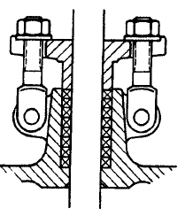
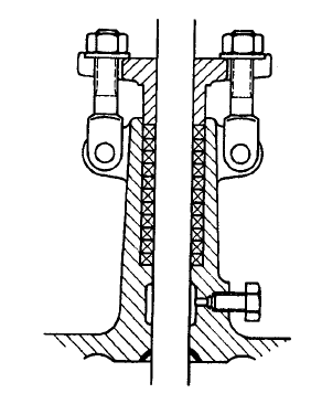
Stuffing Boxes and Back Seating
Pictures show three types of stuffing boxes, which are typical for valves with a rising stem.
The stuffing box shown in below is the basic type in which an annular chamber contains the packing between the gland at the top and a shoulder at the bottom. The underside of the stuffing box carries a back seat which, in conjunction with a corresponding seat around the stem, is used to isolate the packing from the system fluid when the valve is fully open.
The stuffing box shown in Figure is supplemented with a condensing chamber at the bottom. The condensing chamber served originally as a cooling chamber for condensable gases such as steam. In this particular case, the condensing chamber has a test plug, which may be removed to test the back seat for leak tightness.

A third variation of the stuffing box has a lantern ring mounted between two packing sections, as shown in below. The lantern ring is used mainly in conjunction with compression packings and may serve four different purposes:
1. As an injection chamber for a sealant or an extruded or leached-out lubricant.
2. As a pressure chamber in which an external fluid is pressurized to a pressure equal to or slightly higher than the system pressure to prevent any leakage of the system fluid to the outside. The external fluid must thereby be compatible with the system fluid and harmless to the surroundings of the valve.
3. As a sealant chamber in vacuum service into which an external fluid is fed to serve as a sealant.
4. As a leakage collection chamber from which the leakage is piped to a safe location.
The inclusion of the lantern ring, however, increases the depth of the packing column. Sidewall friction reduces the gland packing input load as the packing depth increases, leading to an impairment of the seal integrity
Replacing the lantern ring with a spring is used in rotating pump shaft seals to improve the seal integrity
Applications
Duty:
Controlling flow
Stopping and starting flow
Frequent valve operation
Service:
Gases essentially free of solids Liquids essentially free of solids Vacuum
Cryogenic