Valve Review: Valve Gasket
GASKETS
Flat Metallic Gaskets
Flat metallic gaskets adapt to the irregularities of the flange face by elastic and plastic deformation. To inhibit plastic deformation of the flange face, the yield shear strength of the gasket material must be considerably lower than that of the flange material.
The free lateral expansion of the gasket due to yielding is resisted by the roughness of the flange face. This resistance to lateral expansion causes the yield zone to enter the gasket from its lateral boundaries, while the remainder of the gasket deforms elastically initially. If the flange face is rough enough to prevent slippage of the gasket altogether—in which case the friction factor is 0.5—the gasket will not expand until the yield zones have met in the center of the gasket.
For gaskets of a non-strain-hardening material mounted between perfectly rough flange faces, the mean gasket pressure is, according to Lok, approximately:
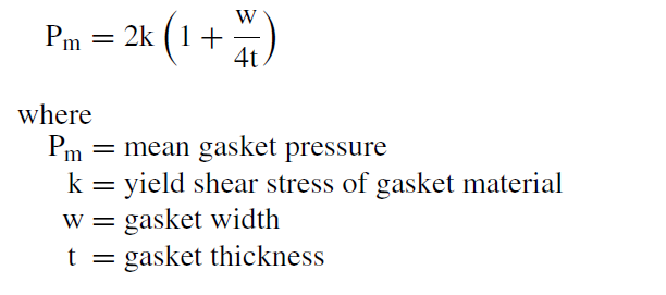
If the friction factor were zero, the gasket pressure could not exceed twice the yield shear stress. Thus, a high friction factor improves the load-bearing capacity of the gasket.
Lok has also shown that a friction factor lower than 0.5, but not less than 0.2, diminishes the load-bearing capacity of the gasket only by a small amount. Fortunately, the friction factor of finely machined flange faces is higher than 0.2. But the friction factor for normal aluminum gaskets in contact with lapped flange faces has been found to be only 0.05. The degree to which surface irregularities are filled in this case is very low. Polishing the flange face, as is sometimes done for important joints, is therefore not recommended.
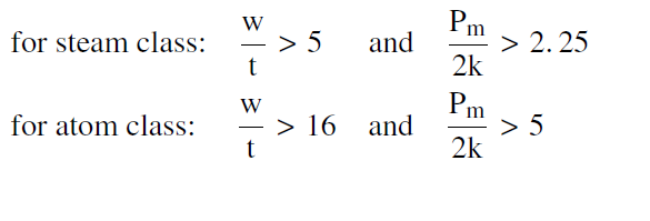
Lok considers spiral grooves with an apex angle of 90◦ and a depth of
0.1 mm (125 grooves per inch) representative for flange face finishes in the steam class, and a depth of 0.01 mm (1250 grooves per inch) representative in the atom class. To achieve the desired degree of filling of these grooves, Lok proposes the following dimensional and pressure-stress relationships.
Gaskets of Exfoliated Graphite
Exfoliated graphite is manufactured by the thermal exfoliation of graphite intercalation compounds and then calendered into flexible foil and laminated without an additional binder. The material thus produced possesses extraordinary physical and chemical properties that render it particularly suitable for gaskets. Some of theses properties are:
• High impermeability to gases and liquids, irrespective of temperature and time.
• Resistance to extremes of temperature, ranging from –200◦C (−330◦F)
to 500◦C (930◦F) in oxidizing atmosphere and up to 3,000◦C (5,430◦F)
in reducing or inert atmosphere.
• High resistance to most reagents, for example, inorganic or organic acids and bases, solvents, and hot oils and waxes. (Exceptions are strongly oxidizing compounds such as concentrated nitric acid, highly concentrated sulfuric acid, chromium (VI)-permanganate solutions, chloric acid, and molten alkaline and alkaline earth metals).
• Graphite gaskets with an initial density of 1.0 will conform readily to irregularities of flange faces, even at relatively low surface pressures. As the gasket is compressed further during assembly, the resilience increases sharply, with the result that the seal behaves dynamically. This behavior remains constant from the lowest temperature to more than 3,000◦C .Thus graphite gaskets absorb pressure
and temperature load changes, as well as vibrations occurring in the flange.
• The ability of graphite gaskets to conform relatively easily to surface irregularities makes these gaskets particularly suitable for sensitive flanges such as enamel, glass, and graphite flanges.
• Large gaskets and those of complicated shape can be constructed simply
from combined segments that overlap. The lapped joints do not constitute weak points.
• Graphite can be used without misgivings in the food industry.
Common gasket constructions include:
• Plain graphite gaskets
• Graphite gaskets with steel sheet inserts
• Graphite gaskets with steel sheet inserts and inner or inner and outer edge cladding
• Grooved metal gaskets with graphite facings
• Spiral wound gaskets
Because of the graphite structure, plain graphite gaskets are sensitive to breakage and surface damage. For this reason, graphite gaskets with steel inserts and spiral wound gaskets are commonly preferred. There are, how- ever, applications where the unrestrained flexibility of the plain graphite gasket facilitates sealing.
Spiral Wound Gaskets
Spiral wound gaskets consist of a V-shaped metal strip that is spirally wound on edge, and a soft filler inlay between the laminations. Several turns of the metal strip at start and finish are spot welded to prevent the gasket from unwinding. The metal strip provides a degree of resiliency to the gasket, which compensates for minor flange movements; whereas, the filler material is the sealing medium that flows into the imperfections of the flange face.
Manufacturers specify the amount of compression for the installed gas- ket to ensure that the gasket is correctly stressed and exhibits the desired resiliency. The resultant gasket operating thickness must be controlled by controlled bolt loading, or the depth of a recess for the gasket in the flange, or by inner and/or outer compression rings. The inner compression ring has the additional duty of protecting the gasket from erosion by the fluid, while the outer compression ring locates the gasket within the bolt diameter.
The load-carrying capacity of the gasket at the operating thickness is controlled by the number of strip windings per unit width, referred to as gasket density. Thus, spiral wound gaskets are tailor-made for the pressure range for which they are intended.
The diametrical clearance for unconfined spiral wound gaskets between pipe bore and inner gasket diameter, and between outer gasket diameter and diameter of the raised flange face, should be at least 6 mm ( 1 in). If the gasket is wrongly installed and protrudes into the pipe bore or over the raised flange face, the sealing action of the gasket is severely impaired.
The gasket filler material must be selected for fluid compatibility and temperature resistance. Typical filler materials are PTFE (polytetrafluoro- ethylene), pure graphite, mica with rubber or graphite binder, and ceramic fiber paper. Manufacturers will advise on the field of application of each filler material.
The filler material also affects the sealability of the gasket. Gaskets with asbestos and ceramic paper filler materials require higher seating stresses than gaskets with softer and more impervious filler materials to achieve comparable fluid tightness. They also need more care in the selection of the flange surface finish.
In most practical applications, the user must be content with flange face finishes that are commercially available. For otherwise identical geometry of the flange-sealing surface, however, the surface roughness may vary widely, typically between 3.2 and 12.5 µm Ra (125 and 500 µin. Ra). Optimum sealing has been achieved with a finish described in ANSI B16.5, with the resultant surface finish limited to the 3.2 to 6.3 µm Ra (125 to 250 µin. Ra) range. Surface roughness higher than 6.3 µm Ra (250 µin. Ra) may require unusually high seating stresses to produce the desired flange seal. On the other hand, surface finishes significantly smoother than 3.2 µm Ra (125 µin. Ra) may result in poor sealing performance, probably because of insufficient friction between gasket and flange faces to prevent lateral displacement of the gasket.
Gasket Blowout
Unconfined gaskets in flanged joints may blow out prior to leakage warning when inadequately designed.
This mode of gasket failure will not occur if the friction force at the gasket faces exceeds the fluid force acting on the gasket in the radial direction, as expressed by the equation:
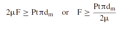
where
µ = friction factor
F = gasket working load P = fluid gauge pressure t = gasket thickness
dm = mean gasket diameter.