Valve Review: Valve Packing
Valve Packings
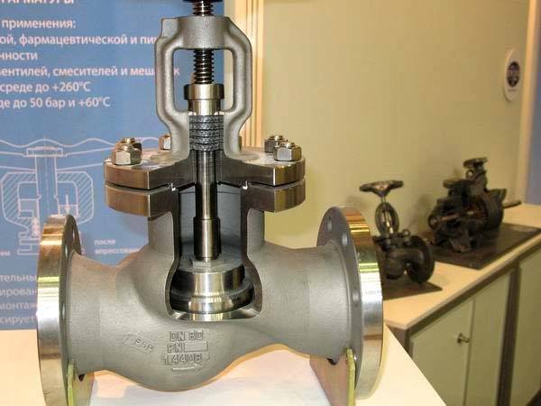
Construction. Compression packings are the sealing elements in stuffing boxes. They consist of a soft material that is stuffed into the stuffing box and compressed by a gland to form a seal around the valve stem.
The packings may have to withstand extremes of temperature, be resistant to aggressive media, display a low friction factor and adequate structural strength, and be impervious to the fluid to be sealed. To meet this wide range of requirements, and at the same time offer economy of use, innumerable types of packing constructions have evolved.
The types of lubricants used for this purpose are oils and greases when water and aqueous solutions are to be sealed, and soaps and insoluble sub- stances when fluids like oil or gasoline are to be sealed. Unfortunately, liquid lubricants tend to migrate under pressure, particularly at higher temperatures, causing the packing to shrink and harden. Such packings must, therefore, be retightened from time to time to make up for loss of packing volume. To keep this loss to a minimum, the liquid content of valve stem packings is normally held to 10% of the weight of the packing.
With the advent of PTFE, a solid lubricant became available that can be used in fibrous packings without the addition of a liquid lubricant.
Asbestos is now avoided in packings where possible, replaced by poly- mer filament yarns, such as PTFE and aramid, and by pure graphite fiber or foil. Other packing materials include vegetable fibers such as cotton, flax, and ramie (frequently lubricated with PTFE), and twisted and folded metal ribbons.
The types of fibrous packing constructions in order of mechanical strength are loose fill, twisted yarn, braid over twisted core, square-plait braid, and interbraid constructions. The covers of the latter three types of packing constructions often contain metal wire within the strands to increase the mechanical strength of the packing for high fluid pressure and high temperature applications.
Sealing action. The sealing action of compression packings is due to their ability to expand laterally against the stem and stuffing box walls when stressed by tightening of the gland.
The stress exerted on the lateral faces of a confined elastic solid by an applied axial stress depends on Poisson’s ratio for the material, as expressed by:
The pressure distribution is also influenced by the mode of packing installation. If the packing consists of a square cord, bending of the packing around the stem causes the packing to initially assume the shape of a trapezoid. When compressing the packing, the pressure on the inner periphery will be higher than on the outer periphery.
When the fluid pressure applied to the bottom of the packing begins to exceed the lateral packing pressure, a gap develops between the packing and the lateral faces, allowing the fluid to enter this space. In the case of low-pressure applications, the gland may finally have to be re tightened to maintain a fluid seal.
When the fluid pressure is high enough, the sealing action takes place just below the gland, where the fluid pressure attempts to extrude the packing through the gland clearances. At this stage, the sealing action has become automatic.
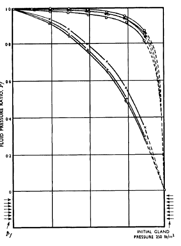
Distribution of Fluid Pressure for Four Rings of PTFE-Impregnated Plaited Cotton Packing Where Pˆ f = Applied Fluid Pressure and Pf = Normalized Fluid Pressure Pˆ f /Pˆ f and Pf = Fluid Pressure.
In the case of high fluid pressures, therefore, the packing ring just below the gland is the most important one, and must be selected for resistance to extrusion and wear and be carefully installed. Also, extra long stuffing boxes for high-pressure applications do not serve the intended purpose.
If the packing is incompressible in bulk, as in the case of soft rubber, the axial packing pressure introduced by tightening of the gland will produce a uniform lateral packing pressure over the entire length of the packing. Fluid pressure applied to the bottom of the packing increases the lateral packing pressure by the amount of fluid pressure, so the sealing action is automatic once interference between packing and the lateral restraining faces has been established.
Unfortunately, rubber tends to grip the stem and impede its operation unless the inner face of the rubber packing is provided with a slippery surface. For this reason, rubber packings are normally used in the form of O-rings, which because of their size offer only a narrow contact face to the stem.
Corrosion of stainless steel valve stems by packings. Stainless steel valve stems—in particular those made of AISI type 410 (13Cr) steel— corrode frequently where the face contacts the packing. The corrosion occurs usually during storage preceding service, when the packing is saturated with water from the hydrostatic test.
If the valve is placed into service immediately after the hydrostatic test, no corrosion occurs.14 H. J. Reynolds, Jr. has published the results of his investigations into this corrosion phenomenon; the following is an abstract.15 Corrosion of stainless steel valve stems underlying wet packing is theorized to be the result of the deaerated environment imposed on the steel surface by the restricting packing—an environment that influences the active-passive nature of the metal. Numerous small anodes are created at oxygen-deficient sensitive points of the protective oxide surface film on the stainless steel. These, along with large masses of retained passive metal acting as cathodes, result in galvanic cell action within the metal. Graphite, often contained in the packing, acts as a cathodic material to the active anodic sites on the steel, and appreciably aggravates the attack at the initial corrosion sites through increased galvanic current density.
Because of the corrosion mechanism involved, it is impractical to make an effective non-corrosive packing using so-called non-corrosive ingredi- ents. Incorporating a corrosion inhibitor into the packing is thus required, which will influence the anodic or cathodic reactions to produce a minimum corrosion rate. Of the anodic inhibitors evaluated, only those contain- ing an oxidizing anion, such as sodium nitrite, are efficient. Cathodic protection by sacrificial metals such as zinc, contained in the packing, also provides good corrosion control. Better protection with a minimum effect on compression and serviceability characteristics of the packing is provided by homogeneously dispersed sodium nitrite and a zinc-dust interlayer incorporated into the material.
High chromium-content stainless steels—especially those containing nickel—exhibit a marked increase in resistance to corrosion by inhibited packing, presumably because of the more rapidly protective oxide surface film and better retention of the passivating film.
Lip-Type Packings
Lip-type packings expand laterally because of the flexibility of their lips, which are forced against the restraining side walls by the fluid pressure. This mode of expansion of the packing permits the use of relatively rigid construction materials, which would not perform as well in compression packings. On the debit side, the sealing action of lip-type packings is in one direction only.
Most lip-type packings for valve stems are made of virgin or filled PTFE. However, fabric-reinforced rubber and leather are also used, mainly for hydraulic applications. Most lip-type packings for valve stems are V shaped, because they accommodate themselves conveniently in narrow packing spaces.
The rings of V-packings made of PTFE and reinforced rubber are designed to touch each other on small areas near the tips of their lips, and large areas are separated by a gap that permits the fluid pressure to act freely on the lips. Leather V-packing rings lack the rigidity of those made of PTFE and reinforced rubber, and are therefore designed to fully support each other.
V-packings made of PTFE and reinforced rubber are commonly provided with flared lips that automatically preload the restraining lateral faces. In this case, only slight initial tightening of the packing is necessary to achieve a fluid seal. V-packing rings made of leather have straight walls and require a slightly higher axial preload. If a low packing friction is important, as in automatic control valves, the packing is frequently loaded from the bottom by a spring of predetermined strength to prevent manual overloading of the packing.
Squeeze-Type Packings
The name squeeze-type packing applies to O-ring packings and the like. Such packings are installed with lateral squeeze, and rely on the elastic strain of the packing material for the maintenance of the lateral preload. When the fluid pressure enters the packing housing from the bottom, the packing moves towards the gap between the valve stem and the back-up support and thereby plugs the leakage path. When the packing housing is depressurized again, the packing regains its original configuration. Because elastomers display the high-yield strain necessary for this mode of action, most squeeze packings are made of these materials.
Extrusion of the packing is controlled by the width of the clearance gap between the stem and the packing back-up support, and by the rigidity of the elastomer as expressed by the modulus of elasticity. Manufacturers express the rigidity of elastomers conventionally in terms of Durometer hardness, although Durometer hardness may express different moduli of elasticity for different classes of compounds. Very small clearance gaps are controlled by leather or plastic back-up rings, which fit tightly around the valve stem. Manufacturers of O-ring packings supply tables, which relate the Durometer hardness and the clearance gap around the stem to the fluid pressure at which the packing is safe against extrusion.
Thrust Packings
Thrust packings consist of a packing ring or washer mounted between shoulders provided on bonnet and valve stem, whereby the valve stem is free to move in an axial direction against the packing ring. The initial stem seal may be provided either by a supplementary radial packing such as a compression packing, or by a spring that forces the shoulder of the stem against the thrust packing. The fluid pressure then forces the shoulder of the stem into more intimate contact with the packing.
Diaphragm Valve Stem Seals
Diaphragm valve stem seals represent flexible pressure-containing valve covers, which link the valve stem with the closure member. Such seals prevent any leakage past the stem to the atmosphere, except in the case of a fracture of the diaphragm.
Dome-shaped diaphragms offer a large uncompensated area to the fluid pressure, so the valve stem has to overcome a correspondingly high fluid load. This restricts the use of dome-shaped diaphragms to smaller valves, depending on the fluid pressure. Also, because the possible deflection of dome-shaped diaphragms is limited, such diaphragms are suitable only for short lift valves.
Bellows-shaped diaphragms, on the other hand, offer only a small uncompensated area to the fluid pressure, and therefore transmit a corres- pondingly lower fluid load to the valve stem. This permits bellows-shaped diaphragms to be used in larger valves. In addition, bellows-shaped diaphragms may be adapted to any valve lift.
To prevent any gross leakage to the atmosphere from a fracture of the diaphragm, valves with diaphragm valve stem seals are frequently provided with a secondary valve stem seal such as a compression packing.
For more topic please visit: www.fctvalve.com