Valve Review: Valve Sealing
FLUID TIGHTNESS OF VALVES
Valve Seals
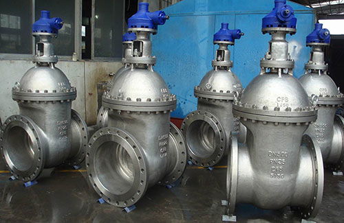
One of the duties of most valves is to provide a fluid seal between the seat and the closure member. If the closure member is moved by a stem that penetrates into the pressure system from the outside, another fluid seal must be provided around the stem. Seals must also be provided between the pressure-retaining valve components. If the escape of fluid into the atmosphere cannot be tolerated, the latter seals can assume a higher importance than the seat seal. Thus, the construction of the valve seals can greatly influence the selection of valves.
Leakage Criterion
A seal is fluid-tight if the leakage is not noticed or if the amount of noticed leakage is permissible. The maximum permissible leakage for the application is known as the leakage criterion.
The fluid tightness may be expressed either as the time taken for a given mass or volume of fluid to pass through the leakage capillaries or as the time taken for a given pressure change in the fluid system. Fluid tightness is usually expressed in terms of its reciprocal, that is, leakage rate or pressure change.
Four broad classes of fluid tightness for valves can be distinguished:
nominal-leakage class, low-leakage class, steam class, and atom class. The nominal- and low-leakage classes apply only to the seats of valves
that are not required to shut off tightly, as commonly in the case for the control of flow rate. Steam-class fluid tightness is relevant to the seat, stem, and body-joint seals of valves that are used for steam and most other industrial applications. Atom-class fluid tightness applies to situations in which an extremely high degree of fluid tightness is required, as in spacecraft and atomic power plant installations.
Steam Class:
Gas leakage rate 10 to 100 µg/s per meter seal length. Liquid leakage rate 0.1 to 1.0 µg/s per meter seal length.
Atom Class:
Gas leakage rate 10−3 to 10−5 µg/s per meter seal length. In the United States, atom-class leakage is commonly referred to as zero leakage. A technical report of the Jet Propulsion Laboratory, California Institute of Technology, defines zero leakage for spacecraft requirements.
According to the report, zero leakage exists if surface tension prevents the entry of liquid into leakage capillaries. Zero gas leakage as such does not exist. Figure below shows an arbitrary curve constructed for the use as a specification standard for zero gas leakage.
Proving Fluid Tightness
Most valves are intended for duties for which steam-class fluid tightness is satisfactory. Tests for proving this degree of fluid tightness are normally 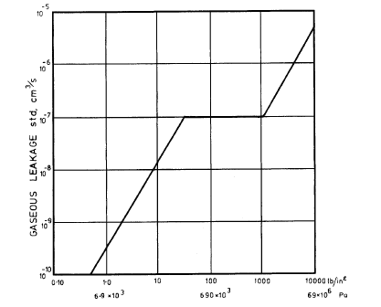
Fig: Proposed Zero Gas Leakage Criterion.
carried out with water, air, or inert gas. The tests are applied to the valve body and the seat, and depending on the construction of the valve, also to the stuffing box back seat, but they frequently exclude the stuffing box seal itself. When testing with water, the leakage rate is metered in terms of either volume-per-time unit or liquid droplets per time unit. Gas leakage may be metered by conducting the leakage gas through either water or a bubble-forming liquid leak-detector agent, and then counting the leakage gas bubbles per time unit. Using the bubble-forming leakage-detector agent permits metering very low leakage rates, down to 1×10⁻² or 1×10⁻⁴ sccs (standard cubic centimetres per second), depending on the skill of the operator.
Lower leakage rates in the atom class may be detected by using a search gas in conjunction with a search-gas detector.
VALVE SEATINGS
The effectiveness of the seating and the subsequent sealing of a valve are very important factors in the selection of a valve for a specific process function. Valve seatings are the portions of the seat and closure member that contact each other for closure. Because the seatings are subject to wear during the making of the seal, the sealability of the seatings tends to diminish with operation.
Metal Seating
Operational wear is not limited to soft seated valves and it can be experienced with metal-seated valves if the process system is carrying a corrosive fluid or a fluid that contains particles. Metal seatings are prone to deformation by trapped fluids and wear particles. They are further damaged by corrosion, erosion, and abrasion. If the wear-particle size is large compared with the size of the surface irregularities, the surface finish will deteriorate as the seatings wear in. On the other hand, if the wear- particle size is small compared with the size of the surface irregularities, a coarse finish tends to improve as the seatings wear in. The wear-particle size depends not only on the type of the material and its condition, but also on the lubricity of the fluid and the contamination of the seatings with corrosion and fluid products, both of which reduce the wear-particle size.
The seating material must therefore be selected for resistance to erosion, corrosion, and abrasion. If the material fails in one of these requirements, it may be completely unsuitable for its duty. For example, corrosive action of the fluid greatly accelerates erosion. Similarly, a material that is highly resistant to erosion and corrosion may fail completely because of poor galling resistance. On the other hand, the best material may be too expensive for the class of valve being considered, and compromise may have to be made.
Table below gives data on the resistance of a variety of seating materials to erosion by jets of steam. Stainless steel AISI type 410 (13 Cr) in heat-treated form is shown to be particularly impervious to attack from
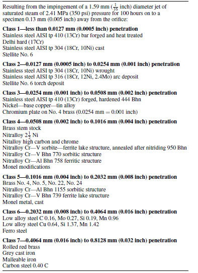
steam erosion. However, if the fluid lacks lubricity, type 410 stainless in like contact offers only fair resistance to galling unless the mating components are of different hardness. For steam and other fluids that lack lubricity, a combination of type 410 stainless steel and copper-nickel alloy is frequently used. Stellite, a cobalt-nickel-chromium alloy, has proved most successful against erosion and galling at elevated temperatures, and against corrosion for a wide range of corrosives.
API Std 600 lists seating materials and their combinations frequently used in steel valves.
Sealing with Sealants
Certain valves have the facility to periodically introduce sealants into the valve seat and stems to maintain an effective seal over an extended period. The leakage passages between metal seatings can be closed by sealants injected into the space between the seatings after the valve has been closed. One metal-seated valve that relies completely on this sealing method is the lubricated plug valve. The injection of a sealant to the seatings is used also in some other types of valves to provide an emergency seat seal after the original seat seal has failed.
Soft Seatings
Soft seats are very effective, but they have limited use at high tempera- tures and pressures. Manufacturers of proprietary soft seats will state the maximum and minimum design pressures and temperatures for which their products are suitable. Some soft seats are also not suitable for some fluids at certain pressures and temperatures.
In the case of soft seatings, one or both seating faces may consist of a soft material such as plastic or rubber. Because these materials conform readily to the mating face, soft seated valves can achieve an extremely high degree of fluid tightness. Also, the high degree of fluid tightness can be achieved repeatedly. On the debit side, the application of these materials is limited by their degree of compatibility with the fluid and by temperature.
A sometimes unexpected limitation of soft seating materials exists in situations in which the valve shuts off a system that is suddenly filled with gas at high pressure. The high-pressure gas entering the closed system acts
like a piston on the gas that filled the system. The heat of compression can be high enough to disintegrate the soft seating material.
Heat damage to the soft seating element is combated in globe valves by a heat sink resembling a metallic button with a large heat-absorbing surface, which is located ahead of the soft seating element. In the case of oxygen service, this design measure may not be enough to prevent the soft seating element from bursting into flames. To prevent such failure, the valve inlet passage may have to be extended beyond the seat passage, so that the end of the inlet passage forms a pocket in which the high temperature gas can accumulate away from the seatings.
In designing soft seatings, the main consideration is to prevent the soft seating element from being displaced or extruded by the fluid pressure.