Control Valve Basics: Sizing and Selection
CONTROL VALVE BASICS – SIZING & SELECTION
A control valve is a power operated device capable of modulating flow at varying degrees
between minimal flow and full capacity in response to a signal from the controlling system.
Control valves may be broadly classified by their function as “on-off” type or “flow regulating” type.
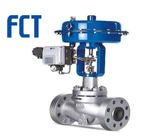
A control valve is comprised of an actuator mechanism that is capable of changing the
position of flow controlling element in the valve. The valve modulates flow through movement of a valve plug in relation to the port(s) located within the valve body. The valve plug is attached to a valve stem, which, in turn, is connected to the actuator. The actuator, which can be pneumatically or electrically operated, directs the movement of the stem as dictated by the external control device. The actuator responds to an external signal which usually comes from a controller. The controller and valve together form a basic control loop.
There are many types of valves available, each having their advantages and limitations. The basic requirements and selection depend on their ability to perform specific functions such
as:
1. Ability to throttle or control the rate of flow;
2. Lack of turbulence or resistance to flow when fully open - turbulence reduces head pressure;
3. Quick opening and closing mechanism - rapid response is many times needed in an emergency or for safety;
4. Tight shut off - prevents leaks against high pressure;
5. Ability to allow flow in one direction only - prevents return;
6. Opening at a pre-set pressure - procedure control to prevent equipment damage; and
7. Ability to handle abrasive fluids - hardened material prevents rapid wear.
This course will discuss the selection process and provide the basic principles of sizing the control valves.
BASIC VALVE TYPES
Valves are available with a wide variety of valve bodies in various styles, materials, connections and sizes. Selection is primarily dependent on the service conditions, the task, and the load characteristics of the application. The most common types are ball valves, butterfly valves, globe valves, and gate valves.
- Ball Valves:
Ball valves are a quick opening valves that give a tight shutoff. When fully open, a ball valve creates little turbulence or resistance to flow. The valve stem rotates a ball which contains an opening. The ball opening can be positioned in the fully open or fully closed position but must not be used to throttle flow as any abrasive wear to the ball will cause leakage when the valve is closed.
Ball valves are considered high recovery valves, having a low pressure drop and relatively high flow capacity.
Best Suited Control: Quick opening, linear
Recommended Uses:
• Fully open/closed, limited-throttling
• Higher temperature fluids
Applications:
• Ball valves are excellent in chemical applications, including the most challenging
services (e.g. dry chlorine, hydrofluoric acid, oxygen).
• General sizes available are 1/2" to 12".
• Compliant with ASME is the flange rating, either 150, 300, 600, 900# or occasionally higher classes, enabling high performance ball valves to withstand up to 2250 psi.
• The operating temperature which is primarily dependent on seats and seals may be rated as high as 550°F.
• Standard valves comply with ASME face-to-face dimensions, making the ball valve easy to retrofit and replace.
Advantages:
• Low cost
• High flow capacity
• High pressure/temperature capabilities
• Low leakage and maintenance
• Tight sealing with low torque
• Easy quarter turn operation- desirable to most operators
• Fairly easy to automate.
Disadvantages:
• Limited throttling characteristics
• Prone to cavitation
• Not suitable for slurry applications due to cavities around the ball and seats. Slurries tend to solidify or clog inside the cavities, greatly increasing the operating torque of the valve and in some cases rendering the valve inoperable.
- Butterfly Valves:
Butterfly valves consist of a disc attached to a shaft with bearings used to facilitate rotation. These are considered high recovery valves, since only the disc obstructs the valve flow path. The flow capacity is relatively high and the pressure drop across the valve is relatively low.
The butterfly valves are used for limited throttling where a tight shut off is not required. When fully open, the butterfly creates little turbulence or resistance to flow. Best Suited Control: Linear, Equal percentage Recommended Uses:
• Fully open/closed or throttling services
• Frequent operation
• Minimal fluid trapping in line
• Applications where small pressure drop is desired
Applications:
• Most economical for large lines in chemical services, water treatment, and fire
protection systems. General sizes available are 2" to 48", although sizes up to 96" are available from certain manufacturers.
• Due to the valve design, incorporating a small face-to-face dimension and lower
weight than most valve types, the butterfly valve is an economical choice for larger line sizes (i.e. 8" and above).
• The butterfly valve complies with ASME face-to-face dimensions and pressure
ratings. This enables the valve to be easily retrofitted in line regardless of the
manufacturer
• The ASME pressure classes adhered to by most manufacturers include 150, 300 and 600# allowing a maximum pressure of 1500 psi.
Applicable Standards:
• AWWA C504 for rubber-seated butterfly valves
• API 609 for lug and wafer type butterfly valves
• MSS SP-69 for general butterfly valves
• UL 1091 for safety butterfly valves for fire protection services
Advantages:
• Low cost and maintenance
• High capacity
• Good flow control
• Low pressure drop
Disadvantages:
• High torque required for control
• Prone to cavitation at lower flows
• Lack of cleanliness and inability to handle slurry applications.
• Generally not rated as bubble tight, and the cavities and leak paths around the disc stem are potential entrapments for fluids and slurries. Some high performance butterfly valves meeting ASME class VI leakage ratings are however available on demand.
- Globe Valves:
Globe valves consist of a movable disk-type element and a stationary ring seat in a generally spherical body. The valve stem moves a globe plug relative to the valve seat. The globe plug can be at any position between fully opened and fully closed to control flow through the valve. The globe and seat construction gives the valve good flow regulation characteristics.
Turbulent flow past the seat and plug, when the valve is open, results in a relatively high pressure drop, limited flow capacity, and low recovery.
Best Suited Control: Linear and Equal percentage
Recommended Uses:
Applications requiring:
• Precise flow regulation
• Frequent and wide throttling operation
• Suited to very high pressure drops
Applications:
• Suitable for most liquids, vapors, gases, corrosive substances
• General sizes available are 1/2" to 8".
• Pressure limitations are relatively high, ranging from 1480 to 1500 psi, dependent on
materials of construction, size and temperature.
• Minimum and maximum temperatures are also very broad ranging from -425°F to
1100°F, depending again on the materials of construction.
• Depending on the specific construction and application, the globe valve may comply
with ASME class II, III, IV, V or VI shut-off requirements.
• Easily automated and available with positioners, limit switches, and other accessories
Advantages:
• Efficient and precise throttling
• Accurate flow control
Disadvantages:
• Low recovery and relatively low coefficient of flow (Cv).
• High pressure drop, higher pump capacity and system wear
• More expensive than other valves
• The sealing device is a plug that offers limited shut-off capabilities, not always meeting bubble tight requirements.
- Gate Valves:
Gate valves use linear type of stem motion for opening and closing of a valve. These valves use parallel or wedge shaped discs as closure members that provide tight sealing.
Best Suited Control: Quick Opening
Recommended Uses:
• Fully open/closed, non-throttling
• Infrequent operation
• Minimal fluid trapping in line
Applications:
• Suitable for oil, gas, air, heavy liquids, steam, non-condensing gases, abrasive and corrosive liquids
• Sizes available range from standard cast configurations as small as 2" to special fabricated valves exceeding 100".
• Standard cast configurations have ASME 125/150 bolting patterns and are rated at
150 psi.
Advantages:
• High capacity
• Tight shutoff
• Low cost
• Little resistance to flow
• Ability to cut through slurries, scale and surface build-ups
• Provide unobstructed flow paths that not only provide high flow capacity (Cv), but even allows slurry, large objects, rocks and items routinely found in mining processes to safely pass through the valve.
Disadvantages:
• Poor control
• Cavitate at low pressure drops
• Cannot be used for throttling
• Relatively low pressure limitation - general pressure limitations are 150 psi at
maximum.
Refer to the summary table at the end of this section to check more valves and their characteristics.
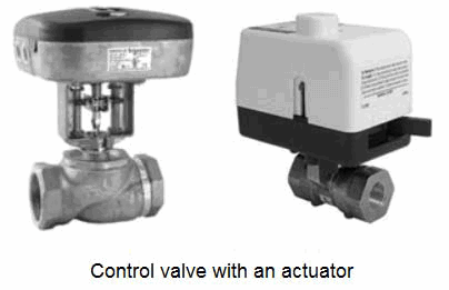
- ACTUATORS
A valve actuator is a device that produces force to open or close the valve utilizing a power
source. This source of power can be manual (hand, gear, chain-wheel, lever, etc.) or can be
electric, hydraulic or pneumatic.
Basic actuators turn valves to either fully opened or fully closed positions. But modern actuators have much more advanced capabilities. They not only act as devices for opening and closing valves, but also provide intermediate position with high degree of accuracy. The valve actuator can be packaged together with logic control and digital communication ability to allow remote operation as well as allowing predictive maintenance data.
Type of Actuators:
Two types of actuators are common: pneumatic and electric actuators.
Pneumatic:
Pneumatic actuators utilize an air signal from an external control device to create a control
action via a solenoid. These are commonly available in two main forms: piston actuators and diaphragm actuators.
• Piston actuators - Piston actuators are generally used where the stroke of a
diaphragm actuator would be too short or the thrust is too small. The compressed air is applied to a solid piston contained within a solid cylinder. Piston actuators can be single acting or double acting, can withstand higher input pressures, and can offer smaller cylinder volumes which can act at high speed.
• Diaphragm actuators - Diaphragm actuators have compressed air applied to a flexible membrane called the diaphragm. These types of actuators are single acting, in that air is only supplied to one side of the diaphragm, and they can be either direct acting (spring-to-retract) or reverse acting (spring-to-extend).
Their range of applications is enormous. For example, the smallest can deliver a few inchpounds of torque where the largest are capable of producing in excess of a million inchpounds of torque.
Electric:
Electric actuators are motor driven devices that utilize an electrical input signal to generate a motor shaft rotation. This rotation is, in turn, translated by the unit’s linkage into a linear motion,which drives the valve stem and plug assembly for flow modulation. In case of electric signal failure, these actuators can be specified to fail in the stem-out, stem-in, or last position.
Commonly used motors for electric actuators include steppers and servos.
• A step motor uses gears with increments in the range of 5,000 to 10,000 at 90 degree rotation for accurate positioning at lower speeds. The disadvantage is that steppers may lose synchronization with the controller when employed in an open loop without an encoder or if they are undersized for an application.
• Servos, by definition, are closed loop and provide superior performance at high speeds, but at a higher cost. High precision screws and anti-backlash mechanics provide accuracies to ten-thousandths of an inch. Standard precisions with standard components range from a few hundredths to a few thousandths of an inch.
Brush DC motors and AC motors are sometimes used with limit switches when positioning accuracy is less critical. The motor is connected to a gear or thread that creates thrust to move the valve. To protect the valve the torque sensing mechanism of the actuator turns off the electric motor when a safe torque level is exceeded. Position switches are utilized to indicate the open and closed position of the valve. Typically a declutching mechanism and hand wheel are included so that the valve can be operated manually should a power failure occur.
Pneumatic v/s Electric Actuators:
The major difference between pneumatic and electronic actuators is the speed of operation.
The two technologies are so different that one cannot be a drop-in replacement for the other.
Each has inherent advantages and disadvantages.
Advantages of Pneumatic Actuators
• The biggest advantage of the pneumatic actuators is their failsafe action. By design of the compressed spring, the engineer can determine if the valve will fail closed or open, depending on the safety of the process.
• Provide high force and speed, which are easily adjustable and are independent of each other
• Have a delayed response which makes them ideal for being resilient against small upsets in pressure changes of the source.
• Most economical when the scale of deployment matches the capacity of the compressor.
• Provide inherent safety and are ideal for hazardous and explosive environment.
• Low component cost and smaller footprint. Prices for non-repairable, rod-type
cylinders range from $15 to $250 depending on body diameter, stroke and options.
Limitations of Pneumatic Actuators
• Maintenance and operating costs can be high, especially if a serious effort has not
been made to quantify and minimize the costs. Maintenance costs include
replacement cylinder costs and plugging air-line leakages whereas the operating
costs include the cost of compressed air, i.e. electricity for the compressor.
Electric actuators:
Advantages
• Provide precise control and positioning in comparison to pneumatic actuators.
• Response time is essentially instantaneous.
• High degree of stability.
• Help adapt machines to flexible processes.
• Low operating cost. Controllers and drivers low voltage circuitry consume power to a far lesser degree.
Disadvantages
• The primary disadvantage of an electric actuator is that, should a power failure occur,
the valve remains in the last position and the fail-safe position cannot be obtained easily unless there is a convenient source of stored electrical energy.
• Higher cost than pneumatic actuators. The total cost ranges from $800 to $3,000 and up. High component costs often deter the use of electric actuators because savings in operating costs compared to pneumatics are often not adequately considered or are outright ignored.
• The actuator needs to be in an environment that is rendered safe. Generally not recommended for flammable atmospheres.
VALVE POSITIONER
Valve positioner is a control device designed to impart sensitivity to the valve and to ensure accurate positioning as dictated by a control signal. It receives an electronic or pneumatic signal from a controller and compares that signal to the actuator’s position. If the signal and the actuator position differ, the positioner sends the necessary power—usually through compressed air—to move the actuator until the correct position is reached.
A positioner may be used as a signal amplifier or booster. It accepts a low pressure air control signal and, by using its own higher pressure input, multiplies this to provide a higher pressure output air signal to the actuator diaphragm, if required, to ensure that the valve reaches the desired position. Some positioners incorporate an electro-pneumatic converter so that an electrical input (typically 4 to 20 mA) can be used to control a pneumatic valve.
Some positioners can also act as basic controllers, accepting input from sensors.

Please see:
https://www.fctvalve.com/libr/an-introduction-to-control-valve
https://www.linkedin.com/company/36166947